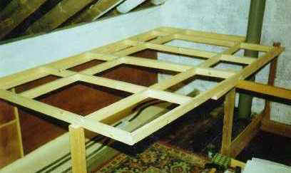
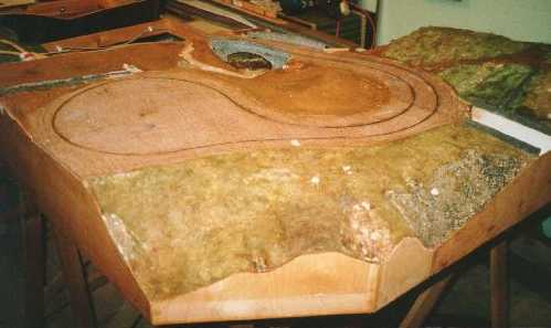
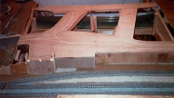
 In the beginning......the first two baseboards. I planned a small-ish self-contained section that would be expandable later. |
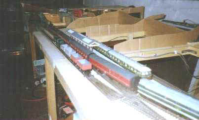
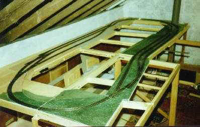 Here there are 4 baseboards with the track laid. The pointwork at front and back shows the planned extension this way, the loop this end will become a Branch. |
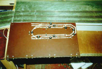 The railway control panel mimic diagram. The switches are for the Cab Control. Gaugemaster controllers have since been added. |
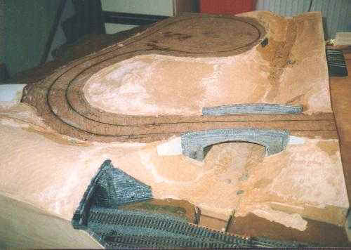
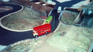
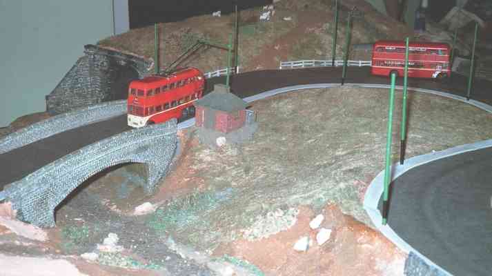
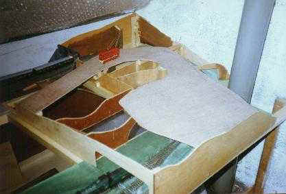 Scenery formers added and the roadway base laid on top of the tunnel. A scratchbuilt model trolleybus gives some idea of scale. |
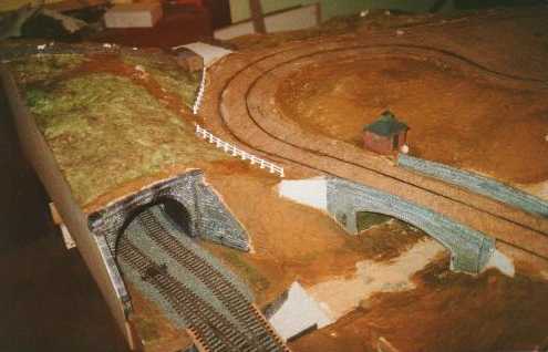
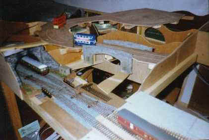 The tunnel mouth and river bridge in place. A Transpennine unit emerges from the tunnel. |
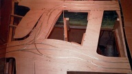
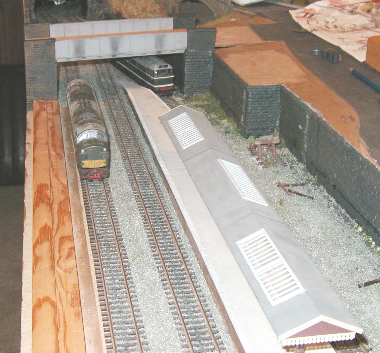
 The three-track station with one platform in place and trial card formers on the second board. These were later altered. |
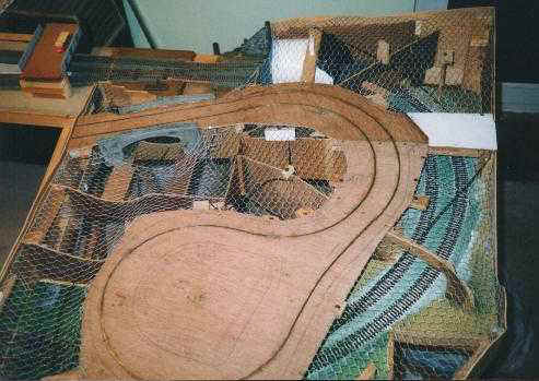 The chicken-wire is added to the tunnel end of the layout to form the hill and valley profile. The bus guide strip has been inserted. |
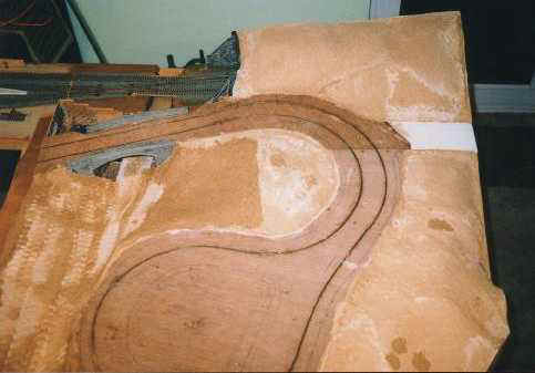 ...and the same view after addition of the bandage and plaster scenery. It is difficult to appreciate the height variation in this view. |
 From the other side, with a few rocks in the streambed and retaining walls added. |
 The first scenery at the moorland end appears... |
 ...and even some small buildings. This one represents a sub-station near the moors. |
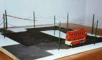 The original test track to check out the trolley steering and the overhead construction. |
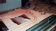
 The second baseboard with guide tracks cut. These are wide so that different vehicles would follow slightly different lines. The railway track has all been ballasted. |
 The guide wires have now been fitted. I started by cutting steel sheet, but found laying several steel wires easier. The points are a piece of shaped steel sheet. |
 View from the other side. The slope is discernible, and was probably greater than it should have been. The buses just make it! |
 View from above the tunnel mouth with road surface in place. |
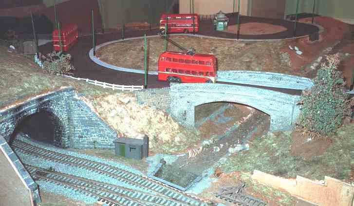 View of the road bridge and tunnel. |
 From the other side of the road bridge. |
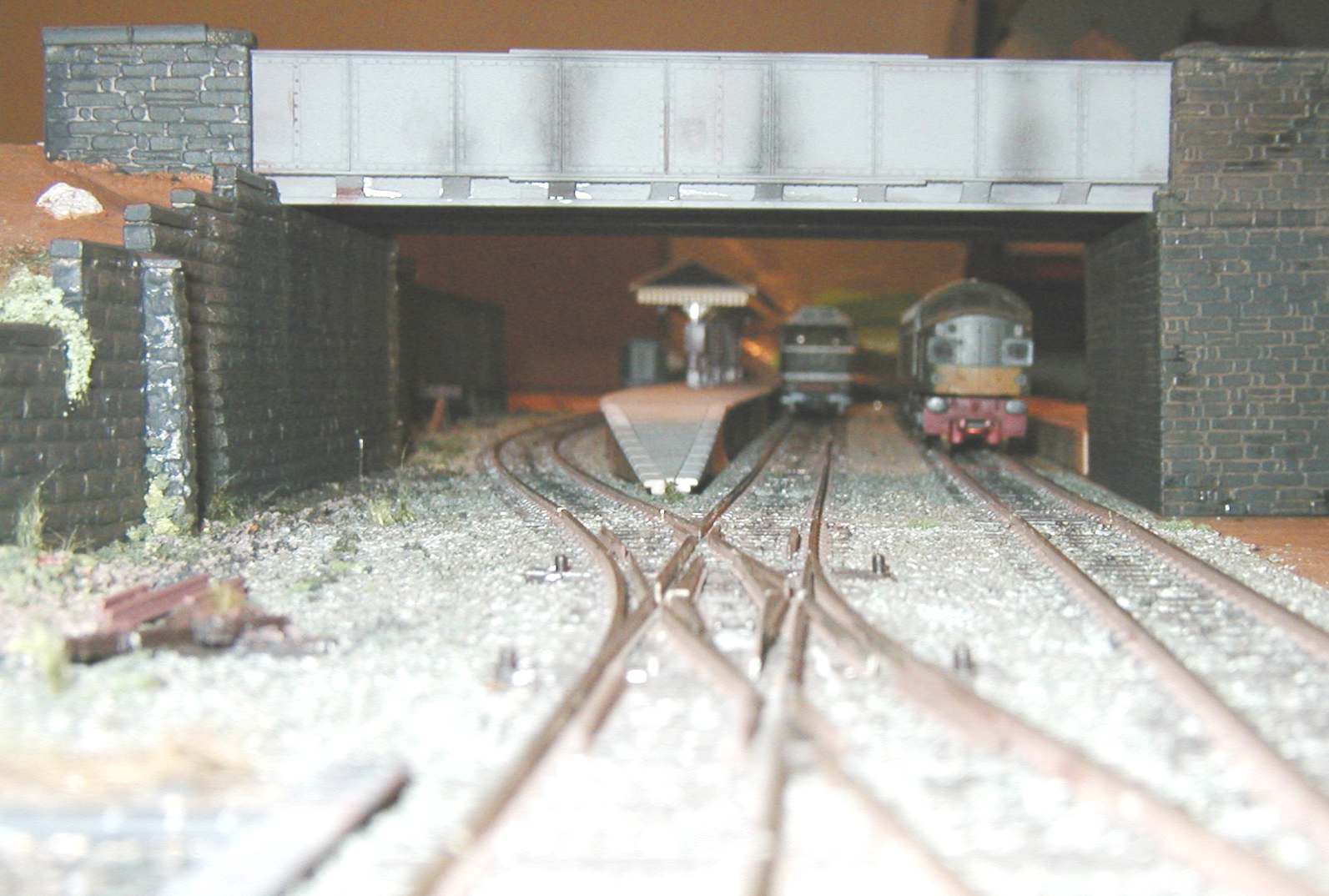 On Board 2, attention turned to the station area, with the building of the retaining walls, a road bridge over the station and detailing and scenic work. This is a worms-eye view of the station approach, taken from the tunnel entrance, after scenery had been applied. (>>) |
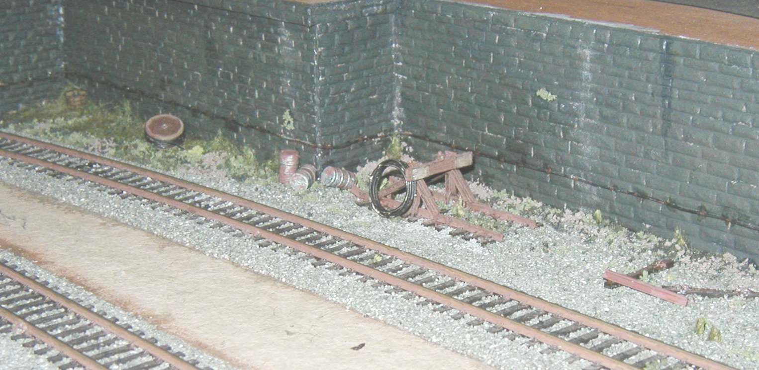 Detail view of the abandoned siding area underneath the new retaining wall. On the right is a birds-eye view looking along the station towards the overbridge. To the right of this is a plain area where the station building will be. Left-hand platform still to be built, as is the footbridge from the station to the platforms. |
 Station area starting to take shape. |